Advanced Settings
Advanced settings are accessed by clicking on
the 'Brain button' in the main display.
PHD2 has a large set of parameters that can be
adjusted to optimize your guiding experience. Although these
are
called "advanced" settings, they are not particularly difficult to
understand, and there may be situations when you need to modify them. All
of
the fields on these forms include "tool tips", small message windows
that describe each field in some detail. Simply
"hover" the
cursor over the field to see the tool-tip. In many cases,
this
will provide all the information you need. Because there are so many parameters available, the Advanced Dialog in PHD2
is organized
into notebook tabs that are activated by clicking on the tab names.
All of the tabs share a common set of 'Ok' and 'Cancel' buttons
at the bottom of the form. Clicking on 'Ok' means that changes
made to any of the tab fields will be put into effect. Clicking
on 'Cancel' discards any changes that were made.
Global Tab
Camera Tab
Guiding Tab
Algorithms Tab
Other Devices Tab
Global Tab
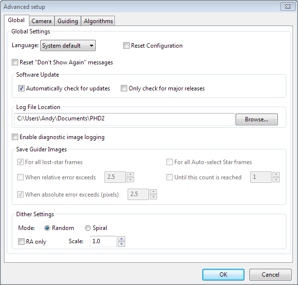
The controls on the
'Global' tab are well-described by their respective tool-tips, but they
are summarized here for completeness:
- 'Language' - determines the language
used in the PHD2 user interface, subject to available localization.
Changing this requires a program restart.
- 'Reset Configuration' - restores all settings to their
initial values as if PHD2 had been freshly installed.
- 'Reset Don't Show Again messages' - restores the display of alert messages if you have previously chosen to not show them.
- Software Update
- Automatically check for updates - allow PHD2
to check for software updates when the program starts up. If no
internet connection is available, checking will be deferred until the
next time PHD2 is run.
- Only check for major releases - don't include development builds when checking for software updates.
See the Software Update section for more information about PHD2 software updates.
- 'Log
File Location' - specifies a directory where PHD2 guide logs,
debug logs, and any diagnostic image files will be stored. The default
location on Windows is the "My Documents" folder associated with the
logged-in user..
- Dither Settings
- 'Random
mode' - tells PHD2 to use a random-number generator to compute both the
size and the direction of the dither, subject to any constraints
imposed by RA-only mode or by the Dec guiding mode being set to 'Off'.
- 'Spiral mode' - tells PHD2 to dither with fixed-size amounts in a clockwise spiral pattern.
This can be a good choice when the imaging camera has
significant fixed-pattern noise or the mount has a troublesome amount
of Dec backlash.
- 'Dither
RA only' - tells PHD2 to dither only on the RA axis.
- 'Dither scale' - an optional multiplier used to adjust the maximum-dither amount specified by the image application. See Dithering Operations
- 'Enable
diagnostic image logging' - used primarily for product support and
diagnosis of problems dealing with the guide camera or PHD2
star-recognition and
measurement. Guide frame images
are captured and logged in a FITs format subject to the filter/trigger
controls in the group-box. Images are saved in sub-folders of the
PHD2 logging directory with the date and time encoded as part of the
sub-folder name. For example, a folder named
'PHD2_CameraFrames_2022-03-03-184542' refers to a logging event that
began on March 3, 2022 at 18:45:42 local time. Individual guide frames
are saved with filenames
that indicate the time the image was captured and the reason the frame
was saved. Since the guide frames are saved in a FITs format, the
header will include other useful information such as exposure time.
Because the logging function is primarily used for
trouble-shooting, the image sub-folders are automatically removed after
30 days. If you wish to keep the images for your own purposes,
you should either rename the sub-folders or copy/move them to a
different directory. When logging is triggered by one of the
"events" - e.g. lost star or large errors - a group of images
(an image set) will be saved, centered in time on the image that
triggered the event. This provides a record of guider
images that will show what the guide star and guide frame looked like
both before and after the unusual condition occurred. The various
triggering and filtering controls are described below and are also shown in the tooltips for the controls:
- 'All
lost star frames' - logs the image set for any lost-star events,
regardless of the reason for the lost star (low SNR, mass-change, etc.)
- 'All
auto-select star frames' - logs the image set for any frames used for
auto-selection of the star, regardless of outcome. Note that any
failed attempts to auto-select a star will always result in a logged
image, regardless of choices made in the user interface.
- 'When
relative error exceeds' - logs the image set when the star deflection
on the current frame exceeds the running-average error by the
factor chosen in the adjacent spin control. For example, if the
average (RMS) error is 0.5 pixels and the current frame's error is 1.5
pixels, the relative error is 3.
- 'When
absolute error exceeds' - logs the image set when the star
deflection exceeds the number of pixels specified in the adjacent spin
control.
- 'Until
this count is reached' - logs images until the count matches the
value of the adjacent spin control. The counter is reset to zero
when the limit is reached.
Since
the images
are saved in an industry-standard format, there are many
astronomy-related applications that can display or analyze them, many
of which are free. Most of the image-capture and image-processing
applications can do that along with other, more specific tools that can
perform detailed measurements on the stars and the optical quality of
the field of view. You can just do a web search to find a list of
applications that support the FITs format for whatever platform you're
using. If you simply want to look at the images to check focus or
see the general quality of the images being returned from your camera,
you can use PHD2 for that. With PHD2 in an idle state -
neither looping nor guiding - just drag-and-drop one of your saved FITs
image onto the main window. The display will then update to show the
image you just dropped. There's
no need for PHD2 to be connected to any of the hardware. You can
adjust the gamma slider, select a star (manually or automatically), and
use the Star Profile tool to view the HFD and profile of the selected
star.
Camera Tab
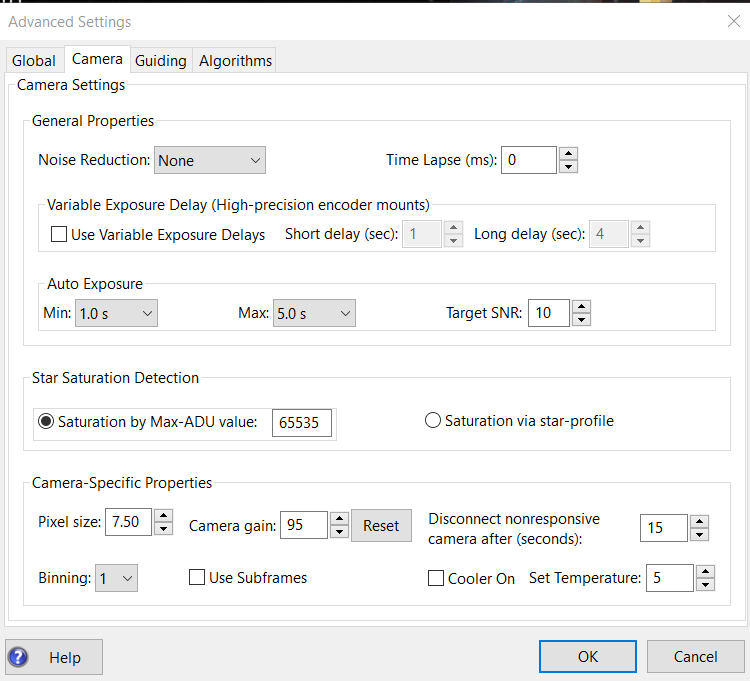
The controls on the 'Camera' tab are used as follows:
- 'Noise
reduction' - specifies the algorithm to use for handling noisy guide
camera images - those for which dark frames are not sufficient.
Choices include None, 2x2 mean, and 3x3 median. Both 2x2 mean
and 3x3
median will reduce the noise considerably. 3x3 median is especially
effective at removing hot pixels and neither will significantly affect
guiding accuracy. However, creating a bad-pixel map is
likely to be a better solution with less impact on your ability to
detect faint stars.
- 'Time lapse' - imposes a fixed delay between
guide exposures. This can be useful if the guide exposures
are
very short and you don't want to overload either the mount or the
camera
link with very high traffic rates.
- Variable
Exposure Delay - very precise/encoder-equipped mounts often
benefit from conservative auto-guiding. This can include use of
medium-long exposure times (4+ seconds) and an additional delay between
guide camera exposures. The goal is to create a slow guiding
"cadence" that is only reacting to tracking changes that aren't already
being handled by the mount encoders or by its pointing model.
Details of the approach can be found here: Variable Delay Guiding
The variable exposure delay controls provide a way to achieve
these goals while avoiding unnecessary delays when the system is engaged in
actions other than "steady-state" guiding for imaging/science
operations.
- 'Use Variable Exposure Delays - enables the feature
- Short
delay (sec) - sets the exposure delay when PHD2 is looping,
star-selecting, calibrating, dithering and settling, or running the
Guiding Assistant. For some mounts, this value should be non-zero
to give the mount encoders enough time to complete their position
adjustments.
- Long delay (sec) - sets the exposure delay when
PHD2 is guiding and not in any of the other states named above.
This delay actually defines the time between the completion of
the last guide command, if any, and the start of the next camera
exposure.
- For both the long and short delay scenarios, the interval
between successive guide camera exposures (and guide commands) will be
exposure_time + guide_pulse_times + delay_value.
- 'Auto Exposure' - these are the settings that control Auto exposure time:, useful for automated imaging or AO guiding:
- Min
Exposure - the minimum exposure time. PHD2 will not set the
exposure
time
less than this value, even if the guide star SNR is higher than the
target SNR value.
If the minimum exposure time is set too low, you are likely to chase
seeing
effects and thereby get poor guiding results. Users of adaptive optics
units might set this to a lower value since rapid small
corrections are more manageable with an AO. Lower values, down to
0.5-sec, can also be tried if multiple guide stars are normally
available in the field of view.
- Max
Exposure - the maximum exposure time. Before a guide star is selected,
PHD2
will set the exposure time to the maximum value. After selection is completed, PHD2
will then incrementally decrease the exposure time until the desired
SNR is reached. The setting should be sufficiently small to allow
PHD2 to adequately handle the tracking errors in your mount.
- Target SNR - this is the average SNR value that PHD2 will attempt
to achieve
by adjusting the exposure time. SNR often fluctuates from frame to frame
even with a
fixed exposure duration, so be sure to account for that when choosing a
target SNR
value. PHD2 will always reject frames when SNR drops below 3.0. The default
value of 6.0 may provide enough of a cushion to prevent fluctuations from causing
the SNR to
go below 3.0 - but double-digit values are recommended. As mentioned in the 'Basic Use' section, SNR is
similar but not identical to the signal-to-noise ratio used in
photometry.
- 'Star
Saturation Detection'
- when identifying candidate guide stars, PHD2 tries to avoid
saturated stars in order to get the most accurate calculations of their
positions. You can assist this process by specifying how the
assessment of saturation should be done:
- Saturation
by ADU value - this is the default option because it relies on the
brightness levels measured by the guide camera sensor. Most
guide camera drivers return image data in either 8-bit or 16-bit
formats even if the camera electronics natively work in 12-bit or
14-bit modes. An 8-bit camera will saturate at a brightness level
of 255 while a 16-bit camera will saturate at levels above 65000.
If you are uncertain about your camera's behavior, you can use
the Star Profile tool to measure the brightest pixel level when taking
exposures of a very bright star. This will quickly tell you if the
camera is returning values in the range of 0-255 or 0-65K and you can
set the saturation value accordingly.
- Saturation via star-profile -
this relies on a less accurate judgment of saturation based on whether
the star profile has a flat top. It is not recommended for normal
applications.
- 'Pixel
size' - The guide camera pixel size in microns. This is needed by PHD2
to compute the
guider image scale and thus report guider statistics in units of
arc-seconds. Refer to your camera documentation to determine
the
correct value for pixel size. If your camera has non-square
pixels, just choose one of the dimensions or input the average of the
two. The pixel size has no effect on guiding accuracy, so a small
amount of imprecision in this parameter won't cause any
problems. If you're using the binning setting in this dialog to
control camera binning, the pixel size should be the native, un-binned
size. Note:
this control may be disabled if the camera and camera driver can report
the pixel size to PHD2 (most can). In that case, the value displayed in the
disabled control represents the device-reported pixel size - it is what
it is. If you're also specifying a binning factor at the camera
driver level rather than in PHD2, the reported pixel size may change as
a result. It is generally better to use PHD2 to set binning (see
below).
- 'Camera
gain' - Sets the gain level for the cameras
that support this feature. Reducing this parameter can help to
reduce the noise level or may allow use of a bright star without
saturation. The range of values and their specific effects are
dependent on the individual camera, so this PHD2 parameter is treated
as a percentage of the range between the minimum and maximum gain
values supported by the camera. For example, if the camera uses
absolute
gain values in the range of 40 to 80, a PHD2 gain value of 50% would
translate to a camera gain of 60. Adjusting the gain level is not
usually required once the configuration has been stabilized, and doing
so will require replacement of dark libraries and bad-pixel maps.
- 'Disconnect
nonresponsive camera after (seconds) - Camera malfunctions will
sometimes occur, often because of faulty USB connections. In many
cases, the camera will not return the requested image data, and PHD2
will appear to "hang." This parameter determines
how long PHD2 should wait for a response after the expected exposure
time has expired. For example, a timeout value of 5 seconds in
conjunction with an exposure time of 2 seconds will tell PHD2 to wait
up to 7 seconds for a response. If the data are not received
within that period, PHD2 will attempt to halt the operation, disconnect
the camera, display an alert message in the main window, then try to reconnect the camera.
Since a hardware/power problem is nearly always the underlying issue, this
recovery attempt won't always succeed. You should be
generous with these timeout values to avoid spurious recovery
actions. Also, if you are using a guide camera that shares
electronics with the main imaging camera, you should set this timeout
to a large
value, well above the maximum expected time for a full-frame download
from the main imager. This is a consideration for users of some of the SBIG dual-chip cameras.
Regardless of whether PHD2 is able to handle the situation
gracefully, the underlying problem is almost certainly in the
hardware or the camera driver and will need to be resolved before
guiding is continued.
- Binning
- for those cameras that support on-chip (hardware) binning, you can
specify the binning that will be used while taking guide exposures.
Detailed information is available here: Use of Binning. This control will
appear only if the camera is capable of on-chip binning and only if the
camera is connected to PHD2. You should always use a separate PHD2
profile for each different binning setting because it affects many
downstream guiding parameters, too many to try to adjust manually.
- 'Use subframes' - For cameras that support this
feature, PHD2
will download only a subframe of each guide
exposure. The subframe shows the region around the star bounded by
the tracking region limits. This is useful for cameras with slow download
times, allowing them to be used more effectively for guiding.
This feature applies to both calibration and guiding.
During initial looping without a selected star, the full
frame is downloaded, but once a star is selected, only this small
subframe is downloaded. If you are using subframes but want to
see the full frame to select a different star, just shift-click
anywhere in the image display window or shift-click on the 'Auto-select
star' button. Using subframes eliminates the option for
multi-star guiding, only a single star can be used with the subframe
option.
- Cooler
controls - a few guide cameras support sensor cooling. These
controls let you specify whether the cooler is on and what the cooler
set-point should be.
Note
that some of the controls in this list will be disabled if the camera
isn't connected to PHD2 or if the camera driver doesn't support the
feature.
Guiding Tab
The
guiding tab shows the parameters used for calibration,
star-tracking, and guiding behavior shared by all of the guide algorithms..
Guide Star Tracking
- 'Search
region' - specifies the size of the "tracking rectangle", in units of
pixels. You may need to increase this value if your mount
does
not perform well or, more commonly, if it's not well-aligned on the
celestial
pole. You may also want to increase it temporarily while using
the Guiding Assistant so that backlash measurement can be done without
losing the guide star. Just remember that an overly large search
region also increases the likelihood that multiple stars will live
within its boundaries, which could lead to guiding problems. The
value is actually a "radius" amount, so a search region of 15 pixels
translates to a square of 30x30 pixels.
- 'Star mass detection' - tells PHD2
to monitor the
brightness and size of the guide star compared to the sky background.
This feature has been deprecated and can generally be left un-checked (default value) for most configurations.
- 'Star mass tolerance' - if the 'Enable' box
is checked, PHD2 will trigger a 'lost star' error if the measured
brightness and size vary by more than this percentage. This
might be useful if you have two stars inside the tracking rectangle and
you want to be sure PHD2
doesn't mistakenly switch stars.
It can also
prevent errors caused by thin clouds, high camera noise, or alpha
particle artifacts;
but it may be unreliable if you are guiding on a faint star. If
you are getting too many 'lost star - mass change'' errors when the star is plainly
visible on the display, try increasing the value of this setting or disable it entirely.
.
- 'Minimum
star HFD' - specifies the minimum half-flux-diameter (roughly the
'size') of a suitable guide star. This is
probably the best way to prevent PHD2 from
mis-identifying clumps of hot pixels as usable guide stars. You
can
determine a suitable value for your system by manually selecting
some small stars that you know are not just hot pixels, then use
the star-profile tool to see the HFD values of those stars.
You'll want to specify a minimum HFD value that allows selection
of legitimate faint stars but not hot pixels. The default value
of 1.5px should work for most configurations but you can adjust it if
needed - for example, if the guide camera pixels are large and too many
candidate guide stars are being rejected because of their apparent
small sizes.
- 'Minimum
star SNR for AutoFind': specifies the minimum SNR value that will be
accepted by the auto-select function for non-saturated stars.
This should only be adjusted by experts because a value that is
too large can result in no stars being selected. It can be used
in situations where you would rather use a saturated star instead
of a faint star that you know from experience will prove to be
unusable. However, many of these situations can be avoided by
getting better guide camera focus, refreshing the dark library, or
slightly increasing the exposure times.
- 'Use multiple stars' - determines whether PHD2 will use more than one star for guiding. See Multi-star Guiding for details.
- 'Auto-selection frame downsample' - can
be used in unusual situations where PHD2 guide star auto-selection is
not recognizing misshapen stars. If this happens, you can try
values greater than 1 to improve the chances of recognizing such stars.
For most users, this property should be left at its default value
of 'Auto'.
- 'Beep on lost star' - specifies whether PHD2 will produce an audible 'beep' sound when the guide star is lost during guiding.
Calibration
- 'Focal length' - the focal length of the guide scope (millimeters). This provides one of
two parameters needed by PHD2
to compute the image scale and thus
report guiding performance in units of arc-seconds. If the focal length value is wrong, some
of the default guiding parameters will not be set correctly, and we
won't be able to help
you assess performance and resolve problems. You should use the
new-profile-wizard to specify focal length as part of defining your
equiipment configuration.
- 'Calibration
step-size' - specifies the duration of the guide pulse that
PHD2
will use during calibration. Its use is described in the
'Auto
Calibration' section of the 'Basic Use' help page. You can
adjust
the value depending on whether the guide star is moving too
quickly
or too slowly during calibration. As a general guideline, it
is best to calibrate within about 20 degrees of the celestial equator
(declination = 0), well above the east and west horizons; and to use a calibration step size that will result
in 8-14 steps in each direction. The 'Advanced...' button
to
the right of this control will launch a calculator dialog that can help
you
compute an appropriate value (see figure below) . As with other
parameters, this value is computed for you as part of running the
new-profile-wizard so there is usually no need to adjust it.
- 'Auto restore calibration' - tells
PHD2 to automatically reload
the most recent calibration data as soon
as the equipment is connected. If
you're using an ASCOM (or Indi) mount connection or have an 'aux-mount'
connection, you probably want to set this option.
Conversely, if PHD2 has no scope pointing
information available, this option should be reset.
The new-profile wizard will ask you how you want to set this
option.
Note that auto-restore is remembered for each separate equipment
profile, and it only has an effect when you load the profile and
connect to the equipment. If you want to force a recalibration
before an individual guiding session begins, there are multiple ways to do that - doing a Shift-Click on
the PHD2/guiding 'Guide' button is the easiest. If you have set the auto-restore
option, you must be sure that the guide camera is not rotated with
respect to the guide scope or the sky.
- 'Assume
Dec orthogonal to RA' - Normally, the calibration process independently
computes the camera angles for both right ascension and declination.
There is no need for great precision on these values, and the
default behavior normally works well. However, if your mount has
very high periodic error, very large Dec backlash, or you are dealing with very bad seeing
conditions, you may want to force the RA and Declination angles to be
perpendicular. If you choose that option, PHD2 will compute the
camera angle for RA, then assert a declination angle that is orthogonal
to it.
- 'Clear mount calibration'
- tells PHD2
you want to clear the calibration data currently being used for the mount and
re-calibrate
before
guiding is restarted. You might do this for a variety of
reasons
- rotating the guide camera or seeing that guiding results are substantially worse than normal, for example.
You can accomplish the same result by doing a Shift-Click on
the PHD2 guiding icon on the main page, which will force a re-calibration.
- 'Use
Declination Compensation' - if PHD2 can get pointing information from
the mount via an ASCOM/Indi connection ('Mount' or 'Aux'), it will
automatically adjust the RA guide rate based on the current
declination.
This box should be left checked except in very unusual
cases where the mount controller is making the adjustment. Don't confuse this option with 'Declination backlash
compensation', which is an entirely different feature.
Shared Guiding Parameters- 'Fast
re-center after calibration or dither' - during calibration or
dithering, the mount may be moved a significant distance from the
initial "lock" position. If you click this checkbox, PHD2 will
move the mount back to the lock position as quickly as possible,
using the largest guide commands permitted by the 'Max Duration'
settings of
your guide algorithms and by the size of your tracking region.
This is only a way to speed up the calibration process, the
use
of this checkbox is completely optional. If you find that
calibration often fails because the star is lost during the fast
re-center,
you should disable this option. That sort of problem may
indicate that you have a large polar alignment error or excessive
periodic
error in RA. You can run the Guiding Assistant to help see what's
causing the problem.
- 'Reverse Dec output after meridian flip' -
tells PHD2 how to adjust the
calibration data after a meridian flip. Some
newer mounts track their 'side of pier' state and automatically reverse the
direction of the declination motor after a meridian flip. Older mounts do not do this. In either case, PHD2
needs to know if the mount will automatically change its behavior based on
side-of-pier. You may have difficulty finding information about
how your mount behaves in this respect, so PHD2 provides the Meridian flip calibration tool to determine the correct setting automatically.
It's also easy to figure out the setting manually with this quick experiment:
- With the checkbox disabled, calibrate on one side of the pier, then move the mount to the other
side.
- If you are guiding via ASCOM or Indi or are using an 'aux mount' connection, just start guiding.
- If
you're guiding only via ST-4 and PHD2 has no scope pointing
information, first select 'Flip Calibration' under the 'Tools' menu,
and then start guiding.
- In either case, if the guiding works normally, leave the box un-checked; but
- if you see guiding run-away in
declination, check the box and repeat the entire procedure, including calibration. You must repeat the procedure, simply checking the box doesn't "fix" anything.
Note:
this procedure must be following in its entirety until you
determine the correct setting. Changing the 'Reverse Dec' setting
only determines what will happen in the future, at the next calibration.
- 'Enable mount guide output'
- this is normally checked because it tells PHD2
to send guide
commands to the mount. There are some
circumstances
where you might want to disable this, usually because you want to
observe the uncorrected behavior of the mount. In most cases, you will be better
off running the Guiding Assistant for these purposes, which
automatically handles this setting for you.
- 'Stop
guiding when mount slews' - prevents PHD2 from trying to continue
guiding when the mount is being slewed, often by an imaging automation
app. It should normally be left checked. Note: this option
is only displayed if you have an ASCOM or INDI mount connection.
Advanced Calibration Calculator
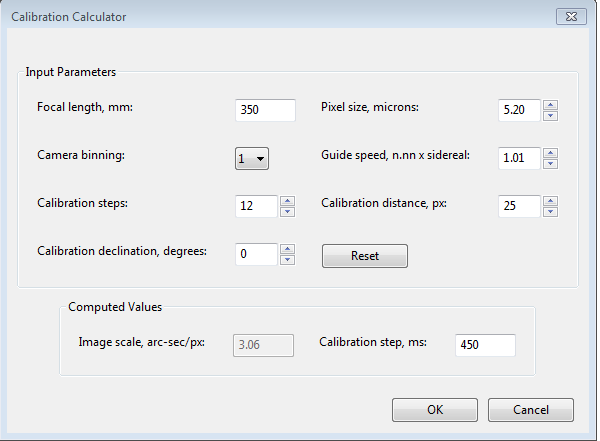
To review or change calibration parameters,
be sure the topmost four edit controls are
correctly filled in. If you have already specified the focal
length and
the camera pixel size via the new-profile-wizard,
those fields will already be populated in this form. If you are
using an ASCOM connection to your mount, the fields for "Guide speed"
and "Calibration declination" will usually show the correct values unless the driver doesn't report them correctly.
Otherwise, you'll need to supply them yourself. The guide
speed is specified as a multiple of sidereal speed - most mounts will
use something
like
1X or 0.5X sidereal, but you can choose something else. Note:
changing the guide speed setting here never changes the guide speed
setting in the mount - that can only be done via the mount driver or
the hand-controller. If this field is already filled in,
changing it will have no effect.
You
can
leave the 'calibration steps' field at the default value of 12, which
is likely to result in a good calibration. Use of a significantly
smaller value raises the likelihood that seeing errors or small mount
errors will cause calibration errors . You should be careful
about increasing this value above 12 because
"bigger" is not always "better". With larger
values, uncorrected periodic error in RA or large drift in
Dec will degrade the accuracy of the calibration. As you
change the values
in these fields, PHD2
will recalculate the value for
the
calibration step-size. If you then click on 'Ok', that value
will
be inserted into the calibration step-size field of the 'Guiding'
dialog and will be used for the next calibration.
Clicking 'Ok' will also populate the focal length and camera
pixel size fields in the 'Guiding' and 'Camera' tabs, so any changes
you
made in the calculator will be reflected there as well. Don't do
this if you are just using the calculator to experiment or check
settings for someone else's system. Clicking on the 'Cancel' button
will close the calculator without changing any of the values in the
curren profile. Again, PHD2 never changes the guide speed setting
in
your mount regardless of what may be entered in the 'Guide Speed' field.
If you've used the
new-profile-wizard to build your equipment profile, there's rarely any
reason to use the 'Advanced" button and the Calibration Calculator
dialog.Algorithms Tab
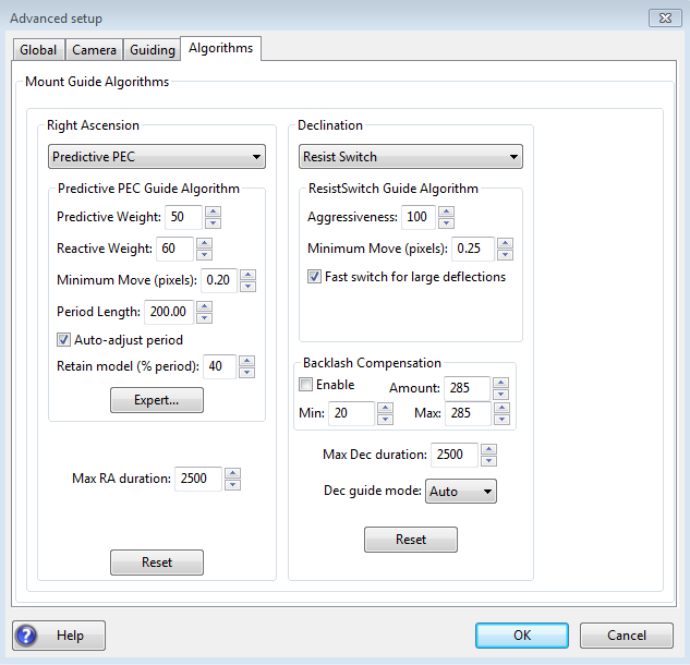
The algorithms tab can be used to select the guiding algorithms you
want and fine-tune the parameters associated with them. The parameters displayed will change significantly if
you
change the algorithm selections. For that reason, all the
parameters related to guide algorithms will be treated together, in a
separate section.
The remaining controls, the ones that are independent of the guiding
algorithm selections, are described below.
- 'Max RA duration' - specifies the
maximum allowed
guide pulse duration for right ascension. You might reduce
this
below the default value if you want to avoid chasing a large
deflection that could be caused by a spurious event (e.g. wind gust,
hot pixel, etc.) .' However, there is rarely any reason for
changing it if you have protected yourself against hot pixels (Minimum
star HFD).
- 'Enable' PHD2 Backlash Compensation - this
controls whether PHD2 will apply a compensation factor when the
direction of declination guiding needs to be reversed.
See section below.
- 'Max Dec. duration' - specifies the
maximum allowed guide pulse duration for declination (same as above but
for declination). NOTE: if Backlash Compensation is enabled, this setting will be managed by the backlash compensation algorithm
- 'Declination
guide mode' - gives you additional control over declination
guiding. Declination guiding is not like RA guiding because the
tracking errors are not caused
by imperfections in your mount's drive system - the Dec motor is idle
during normal sidereal tracking, running only in response to short Dec guide commands. Instead, tracking errors in
declination are caused by polar
alignment error, mechanical flexure, wind, binding or dragging of cables, or
unwanted movement of the guiding assembly.
Absent these mechanical problems, declination
tracking should be smooth and mostly uni-directional assuming
there is no over-shoot from an
earlier correction. The default value of 'auto' tells PHD2
that
some reversals in direction are acceptable, subject to the behavior of
the various guiding algorithms. However, if your mount has severe
declination backlash, you may want to prevent direction reversal
altogether. You could then select either 'north' or 'south'
to
restrict corrections to only that direction (uni-directional Dec
guiding). Keep in mind,
however, that an over-shoot in correction with one of these modes
might leave the star positioned off-target for an extended period of
time. So you'll probably want to use conservative
aggressiveness values for either 'North' or 'South' modes and you may
want to intentionally degrade the polar alignment to help keep the
drift rate larger than the deflections caused by seeing.
Finally, a choice of 'off'' here disables declination guiding
altogether, an appropriate choice for simple tracking mounts that don't
support Dec guiding.
- 'Reset'
- resets the guiding parameters for the selected RA or Dec algorithm to
their default values. Min-move settings will be set using the
same algorithm employed in the new-profile-wizard. If you
previously used the Guiding Assistant to adjust the min-move settings,
you should repeat that procedure.
Declination Backlash Compensation
Most
commonly-used mounts have some backlash in declination.
You can find a brief discussion of backlash mechanics here: Dec Backlash
Backlash causes a delay whenever there is a change in direction
of
the Dec guide commands. During this interval, the declination
gears aren't fully engaged and the axis doesn't move in response to the
guide commands. Many mounts have settings for backlash
compensation but these should not be used for guiding - they are
typically intended for visual use only.
Because the actual amount of compensation needed at any given
time depends on the pointing position and the mechanical load on the
system, a fixed value will usually result in oscillations that never
stabilize. Reasons for the positional dependency include
uneven gear wear or significant imbalance of the scope in
declination. The backlash compensation implemented by PHD2 is
adaptive, meaning that the compensation amount is adjusted up or down
depending on the measured results. Before enabling this feature,
you should run the Guiding Assistant and measure the declination
backlash - the time delay required to fully reverse direction in
declination. Keep in mind, the higher the guide speed setting in
the mount (e.g. 0.9x sidereal), the smaller this delay will be.
If the measured amount is 3 seconds or less, the Guiding
Assistant will recommend trying backlash compensation. If you
apply that recommendation, the backlash compensation settings will be
handled for you automatically. The UI controls for backlash
compensation include settings for 'minimum' and 'maximum' compensation
amounts. These effectively limit the range of the adjustments
that are made to the starting compensation value. If you're
experienced with your mount's behavior, you can adjust these settings
manually to be sure the compensation stays within a range that you
know works well. Otherwise, you should just leave these at their
default values. The backlash compensation algorithm will
generally work well if the backlash is less than a few seconds and the
mount doesn't have other significant mechanical problems. You
should expect a short period of instability when guiding starts
because the initial state of the Dec gear system is unknown - just let
it stabilize before you actually start imaging. If you see
recurring periods of Dec oscillation or the axis won't settle down,
disable the compensation feature and submit your debug log file to the
PHD2 support forum. Other Devices Tab
If
you are using either an adaptive optics or rotator device, the "Other
Devices" tab will be shown. A general discussion of using an AO for guiding can be found here: AO Guiding The upper section deals with the AO
device if one is being used. You
can use these parameters to control the
calibration process and the manner in which 'bump' operations are done.
The 'calibration step' field tells PHD2 the amount to move the
tip/tilt element in each of the up/down/left/right directions, in
units of AO steps, during calibration. The guide star position is measured at the
beginning and end of each leg of the calibration, and the 'samples to
average' parameter tells PHD2
how many samples to take at each of these
points. Averaging images is important because the seeing will
always cause the guide star to "bounce around" a bit. As
discussed elsewhere, the AO unit can make corrections
only within a limited range of guide star movement. You
will want to initiate mount 'bump' corrections before these limits
are actually reached, and the 'bump percentage' field is used for that
purpose. To move the mount, the full bump correction is
accomplished in steps - the 'bump step' field controls the size of
these increments. If the bump operation has begun and the guide
star remains outside the "bump percentage" area, PHD2
will increase the
bump size until the guide star is back within that range.
Additional movement from that point to the center position
will
continue at the specified "bump step size". This complexity is
required in order to maintain good guiding, with no elongated stars,
even as the mount is being bumped. During the bump operation, the
AO is continuing to make corrections, so the long "mount bump" is
continuously offset by adjustments in the AO. The 'AO
Travel' field specifies the number of steps the AO can make on each
axis. The default value works well for most SX AO devices but in
some cases it may be too large. If you encounter problems during
AO calibration where the AO hits its limits, you can adjust the 'AO
Travel' amount downward.
The
'Bump on dither' option tells PHD2 to bump the mount when a dither
command is received and thus move the guide star back closer to the
center position of the AO. The
option to enable or disable AO guide commands operates independently
from the 'Enable mount guide output' checkbox in the Guiding tab.
So
you can
independently enable/disable either the guide commands to the tip/tilt
device or the
'bump' guide commands to the mount. The same principle holds for
the 'Clear AO calibration' option - that will force a recalibration of
the AO without affecting calibration of the mount. The 'Mount
Backlash Compensation' controls let you apply PHD2 Dec backlash
compensation when mount bumps are done. This can help speed up
large dither operations, but it's only appropriate if the mount has a
limited amount of Dec backlash. You should use the Guiding Assistant to
measure your Dec backlash and see what it recommends with regard to
using Dec backlash compensation. The backlash compensation value
cannot be adjusted automatically when the AO is being used so it is a
good idea to specify a value that is perhaps 1/2 the value suggested by
the Guiding Assistant.
When an AO is in use, the 'Algorithms' tab will only show choices for controlling the tip/tilt optical element in the AO
device
itself.
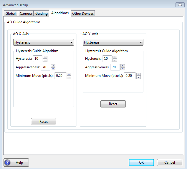
Since
the
AO is not trying to move a heavy piece of equipment, you can
afford to be more aggressive in your guide algorithm choices.
The default algorithms for an AO are 'Hysteresis'', which provides an easy way to control damping and
aggressiveness. If
you use a different algorithm, you should
probably start with a high level of aggressiveness there as well.
The other, shared guiding parameters normally displayed on the
'Algorithms' tab will not be shown for the AO because they aren't used
to control the device.
The rotator device has only
one parameter which lets you match the behavior of the device to the
ASCOM notion of positive and negative angles. The "Reversed"
checkbox can be used for
optical systems that reverse the image, usually because they have an odd number
of mirrors. The direction and amount of rotation is used to
adjust the calibration data, so PHD2 follows the ASCOM standard:
"the rotator position is expressed as an angle from 0 up to but
not including 360 degrees, counter-clockwise against the sky."
Experimentation is likely to be the quickest way to determine if
the box should be checked.