It’s difficult to get far in imaging and guiding without
coming to grips with astronomical seeing.
This is a complex subject so only the bare minimum can be covered here. “Seeing” is the term given to the positional jitter
and sudden brightness changes of stars we see (or photograph) through a
telescope. With the naked eye, we see
this as “twinkling” because our eye can’t resolve the tiny positional movements
of the star. It is atmospheric
turbulence, caused by the movement of thermal cells at various levels in the
Earth’s atmosphere. Light is refracted as it passes through each atmospheric
cell, so when you look at a star, you’re really looking up through a column of
air that is behaving like a column of little lenses. The refraction of the light by each cell
depends on its temperature, and the cells generally have different
temperatures. And because the atmosphere
is very dynamic, these elements are all moving around at various speeds, coming
into and then leaving the column of air you’re looking through. Particularly with longer focal lengths, this
atmospheric seeing is the single biggest source of the guide star movement we
see with a properly working mount, and it can’t be “guided out”. The
movement of the atmospheric cells means
the guide star position is changing at rates of 10’s to 1000’s of times
per
second, and amateur-grade equipment, even adaptive optics devices,
can’t react
quickly enough to correct for it. Professional observatories are able
to do it
to a large extent by employing very expensive measurement devices,
artificial
stars, and mechanisms that can both deform the mirror and shift the
image at
very high frequencies. For these observatories, most
of the seeing disturbances originate in the upper layers of the
atmosphere and those are the layers that are used for seeing
models and most seeing forecasts. For amateurs and
especially for those who image from urban or backyard locations, seeing
problems also arise from sources close to the telescope. Heat
convection from hard ground surfaces or neighboring rooftops create
lower frequency "boiling" behavior that degrade guiding and imaging
performance. Ground-level heat can also create tube currents and
uneven layers of hot air inside the telescope tube - these also can
masquerade as low-frequency seeing effects. Users should do what
they can to avoid or mitigate these situations and, when working in
locations with high daytime temperatures, should expect it will take
many hours after sunset for the equipment temperatures to equilibrate.
The high-frequency, seeing-induced star motion seen by the
guide camera is strongly affected by the length of your guide exposure. Look at the following plot to see how the observed range
of guide star motion decreases as the exposure time is increased:
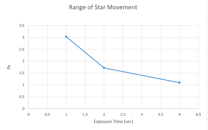
Essentially, the camera sensor is averaging the changing light pattern of the star and smoothing the result. Measurement uncertainty is still present because of under-sampling, but the longer exposures make it easier for PHD2 to isolate and identify the lower frequency errors that really can be improved through guiding. Obviously, there is a practical upper limit to the exposure time. Typically, it will be limited by the length of time your mount can run on its own without needing a correction. Small errors from periodic error, drift, flexure and other sources need to be corrected before they become large enough to ruin an image. Finding the right balance will always depend on both the seeing conditions and the quality of the equipment. As a starting point in PHD2, we typically recommend using exposure times of around 2 seconds and lower exposures of at least 0.5 sec only if the mount requires it and then only if guiding is active on multiple stars.
In order to reduce fixed-pattern noise
and hot pixels, imagers often move the telescope by very small amounts between
exposures – this is called dithering. Dithering is always controlled by the imaging
app because it is the only one that can suspend exposures with the main camera
while the pointing position is being shifted. PHD2’s only role in this is
to issue guide commands that will accomplish the requested shift in position –
it is simply doing that it’s told. The small shift in pointing position is accomplished by PHD2 in two steps:
1. Change the lock-point of the primary guide star by the
amount requested by the imaging app.
2.
Use the normal guiding routines to move the primary
guide star to the new lock-point
The size of the dither is controlled by the imaging
app, at least indirectly. The app may
let you specify the maximum size of a dither, typically in units of
pixels. In that case, PHD2 interprets this
as the upper range of random values between zero and this limit. The randomizing process is done to insure
that dithering doesn't follow a simplistic back-and-forth pattern or shift the
frame back to a location where it has previously been. For some applications that do
PHD2 dithering, you can't specify the maximum amount directly - you are perhaps
limited to choices like small/medium/large and the max dither amounts will have
preset values. For that reason, PHD2 has a dither scaling parameter in
the 'Global' tab of the Advanced Settings dialog. It is basically a
multiplier term that lets you adjust the range of dither amounts that are
possible. So a scale factor of 1 doesn't change the preset value at all,
a value of 10 multiplies it by 10X, etc. If you're using an app that lets
you specify the maximum amount directly (e.g. PHD_Dither), you should leave the
dither scale set to 1.0. Otherwise, you can adjust the scale factor if
you aren't happy with the overall range of dithering you're getting with one of
the small/medium/large choices..
It’s
up to the imaging app to determine
when the guiding has settled down and it’s time to start the next
exposure with the main camera. To make this easier for
authors of the imaging apps, PHD2 provides
some extra measurement information on how the settling process is
proceeding. This information doesn’t need to be used by the
imaging app,
it is entirely optional. In order to take advantage of this help,
the
imaging app specifies what level of stability it wants to see in order
to
decide that the dithering activity has settled down. There are
three
settling parameters for doing this:
1.
The maximum amount of guide star
position error that is considered acceptable – call that position tolerance, PT
2.
The length of time that must elapse during
which the guide star position error stays below the position tolerance – call
that the evaluation time, ET
3.
The maximum amount of time that can be tolerated
before the measurement process is terminated and the dither is declared to be
“done” regardless of the guiding stability – call that the time-out period, TO
To state this in a sentence, the
settling process is “done” when the guiding error is <= PT for ET
seconds or, if that condition is never satisfied, after TO seconds have
expired. When this evaluation process is complete, PHD2 sends a message
to the imaging app saying settling is done. This is all just extra credit
for PHD2, normal guiding is being done from the time the lock-point is moved.
Of course, the specification of these
parameters, PT, ET, and TO,
is up to you and the values
have to be chosen intelligently. Your imaging app may not expose all of
these parameters in its user interface or it may give them different
names. If you’re dithering by large amounts
with a low-performance mount, you have to expect it will take a long
time to
settle down. If you specify a PT value that is too large or an ET
value that is too small (overly lax parameters), the imaging app may start the
next exposure too soon and you could get streaked stars in the image. The same problem could occur if you specify a TO
value that is too short. Conversely, if you specify a PT value
that is too small or an ET value that is too long (overly demanding
parameters), then all of your dithers will incur a delay of TO
seconds and settling will "fail" – you are asking too much from
your mount. A sensible approach is to look at your past performance to
see how well your mount responds under typical seeing conditions with the size
of dithering you want to use. If your mount has a lot of Dec backlash,
you should see how long it takes for guiding to settle down when the direction
of the Dec guide command is reversed. The ET and PT
values
should reflect the guiding performance you normally get with your setup
with a
little bit of slack to avoid wasting time. Occasional timeouts
during settling are fairly common and typically don't cause problems
but you should check your guide logs using the LogViewer tool to be
sure the main camera exposure isn't being started while large
corrections are still being done by PHD2.
PHD2 also supports different choices
for how the star is moved in RA and Dec.
With the default settings, the mount will be shifted in RA and Dec by
different random amounts as described earlier.
If you choose “spiral mode”, the guide star will be moved in a pattern
that eventually produces a spiral pattern around the original lock-point. This automatically reduces the number of Dec
reversals and can be a good choice if your mount has substantial backlash. In
this mode, there is no randomizing process involved, each dither has the size
specified by the imaging app. Alternatively,
you can choose the RA-only option and eliminate Dec reversals
altogether, but
this may not be a good choice if your imaging camera has a lot of
fixed-pattern
noise. When deciding how to specify the size of the
dithers, you need to take into account the image scales of both your
guiding setup and your main imaging system. For CMOS imaging
cameras, you may find advice to do large dithers, perhaps 10-20 pixels.
But this means 10-20 pixels on the main camera sensor, not the
guide camera sensor, so you need to calculate how much movement
is needed on the guide camera to achieve the desired displacement on
the imaging camera. It will quite often be less.
If your mount has a substantial amount of declination backlash in the mount, you may be guiding in only the north or south Dec direction. If PHD2 receives a command to dither in declination while you're operating in this mode, it will temporarily allow guiding in both Dec directions until the dither and settling are completed. It will then revert to the original north/south-only guiding mode. If you don't want this behavior, you should restrict dithering to 'RA-only'. All of the PHD2 dither controls are contained on the 'Global' tab of the Advanced Settings dialog.
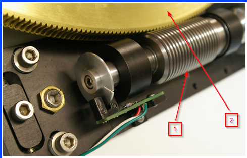
Periodic error is most often caused by very small machining errors in the various components of the RA drive system. One part of a typical drive system is shown here:
Credit: Mathis Instruments
A high-precision worm gear (arrow 1) is used to drive the
much larger worm wheel (arrow 2). The
latter is attached to the RA shaft and when the mount is tracking at the
sidereal rate, the worm wheel will complete a rotation in one sidereal day
(23.934 hours). In order for this
tracking to be perfect, all the following conditions must be met:
Identical pitch and spacing for every thread in the worm gear
Rigid attachment of the worm gear to the mounting plate with
no flexure or movement of the gear or the mounting blocks
Identical shape and spacing of every tooth in the worm wheel
Worm wheel perfectly round and perfectly centered on its
axis of rotation
These are actually just a few of the necessary conditions, but it’s obvious that this level of precision is not likely to be present in most amateur mounts. The machining of the worm gear is usually the biggest challenge so tracking errors often originate there. The worm gear turns at a constant rate during sidereal tracking and the time it takes to make one full revolution is called the “worm period”. Worm periods vary among different mounts but generally fall in the range of 4 to 10 minutes. A machining inaccuracy on one of the worm threads will therefore make its presence known once in every worm period. Of course, many of the worm gear threads are likely to have some inaccuracies and each will make its own contribution to tracking error once during the worm period. When the tracking error is graphed over a single worm period, the result is usually a curve that is roughly sinusoidal with varying slopes, peaks, and valleys – this is what is known as periodic error. Here’s an example:
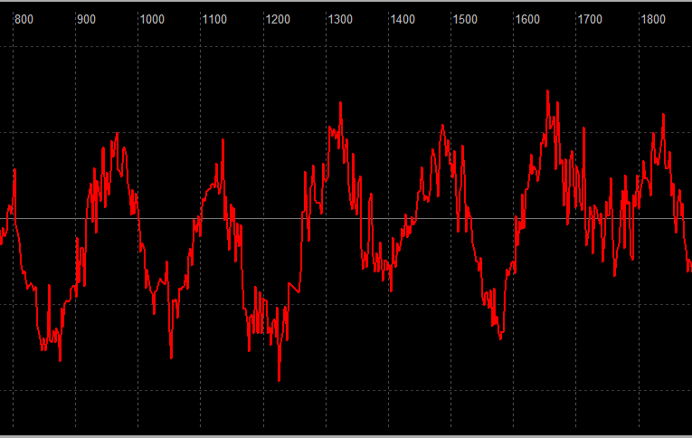
Notice the high-frequency movements caused by seeing that
are not part of the mechanical periodic error.
There are other gears in the RA system, often a series of
gears that lie between the motor and the worm gear. These are required to convert from the native
speed of the motor to the slower rotation speed of the worm gear and also to
generate the torque needed to drive the worm gear. Each of these components will have machining
inaccuracies of its own and will contribute to cumulative tracking errors of
the mount. Many of these components will
introduce errors on shorter time periods than the worm period. Some mounts use drive belts to sidestep some
of these “upstream” gear inaccuracies but those can introduce errors of their
own – incorrect tensioning, lateral movement of the belt on spindles, etc.
Periodic error correction (PEC) in the mount firmware is beneficial to auto-guiding if the feature is implemented correctly. Unfortunately, this isn’t always the case. But when done correctly, periodic error correction handles some tracking errors before they are seen in the guide camera image. These corrections are predictive, based on a model of the mount’s PE, as opposed to being reactive like normal auto-guiding. The net result is that PHD2 has less work to do to keep the RA axis on-target. Even when the implementation in the mount is done well, calculation of a high-quality PEC curve must be done carefully using an application specific to the purpose. During the measurement process, the app must filter out seeing-induced guide star movements to produce a smooth correction curve that represents samples across multiple worm periods. It must also be aware of the worm period and the various harmonics in the mount drive system in order to apply corrections only for those tracking errors that are harmonic - i.e. errors with frequencies that are integer multiples of the worm frequency. If the PE correction curve is poorly constructed, the RA tracking can be worse than using no PEC at all.
If PEC isn't available for your mount or is badly implemented, you can use the PPEC guide algorithm in PHD2. PHD2 Predictive PEC
Backlash can occur when the direction of motion on an axis is reversed. The telescope may not immediately start moving in the reverse direction even though the motor is turning. The usual cause is loose meshing of the gears in the drive train. For auto-guiding, this problem doesn't affect guiding in RA because the RA drive system is continuously moving the axis west as it tracks the sky - it never reverses direction because of guiding. But it is a common source of trouble for Declination because the Dec axis is mostly idle during guiding, running only in short bursts in response to guide commands to move the scope north or south.. A simple picture of what causes backlash is shown here:
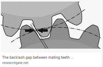
This diagram shows two spur gears, but the basic principle also applies to worm gear and worm wheel pairs. In the diagram above, assume the bottom gear is the drive gear currently rotating counter-clockwise. The teeth on the drive gear are in contact with the teeth on the driven gear above it and the latter is being driven clockwise. But the arrows show that the surface on the trailing edge of the drive gear tooth is not touching the matching tooth on the driven gear - there is a small gap. So when the drive gear reverses direction, there will be a short period of time before the gears are fully meshed and the driven gear starts turning in the opposite direction. The "reversal delay" in this case is caused by simple backlash. Some amount of gap is generally required to avoid binding in the gear system and to allow room for lubricant and thermal expansion. When the mesh is too tight, the axis may exhibit stiction (static friction), a situation where the axis will not move smoothly and freely or is difficult to get moving from a stationary state. Stiction on the Dec axis can result in a pattern of an initial reversal delay that looks like backlash followed by a large over-shoot once the axis finally starts moving. Other than mistakenly having backlash compensation enabled in the mount software, stiction is the most common cause of oscillations in Dec guiding.
The Guiding Assistant will measure how the Dec axis behaves when it is forced to reverse direction. It is only capable of measuring the "reversal delay", the amount of time it takes to change direction and get the axis rotating at the expected rate. It isn't always possible to distinguish whether the problem is backlash, stiction, or both; but the graph produced by the GA can often provide clues. This behavior can also be seen during normal guiding sessions that don't employ the large guide pulses used by the GA. If the reversal delay is large, say above 3 seconds, it's probably best to try adjusting the Dec drive system. If the delay is less than that, the PHD2 Dec Backlash Compensation feature will probably be able to handle Dec reversals fairly well. Note that the amount of delay is inversely proportional to the guide speed in the mount - as the guide speed is increased, the reversal delay decreases. This is one of the reasons we recommend using guide speeds of at least 0.5x sidereal.
The reversal delay is usually not a constant value for the mount. Instead, it often depends on the pointing position of the scope and the balance of the scope on the Dec axis. As mounts age, the gears wear and for Dec, the wear will be greatest where the scope spends most of its time during imaging. For northern observers, that is probably in the Dec range of 0 to 40 degrees. With older mounts especially, the reversal delay can be quite different in those pointing positions than, for example, regions closer to the pole. This is another reason why the PHD2 Backlash Compensation feature is a better choice than any fixed-size compensation that is programmed in the mount controller.
Mounts with very accurate absolute encoders and detailed
pointing models often allow imaging without any guiding at all. But there are limitations to how long this
can be done without needing some guiding corrections. The goal in this scenario is to provide a “backup”
guiding mechanism that won’t conflict with the inputs from encoders and
pointing models and will still improve the overall result. The recommended strategy for accomplishing
this is as follows:
1.
Keep the frequency of guide commands as low as possible.
These mounts can actually be quite “busy” with corrections coming from encoders
and fine-grained pointing models, none of which are visible to ASCOM applications.
A slow guiding frequency will minimze the potential for creating instabilities in
these functions from external guide commands.
2.
Be especially carefully to avoid chasing the seeing – this is most easily
done by using moderate-length or long guide camera exposures and generous
min-move settings.
In previous PHD2 releases, users have been able to approximate
this approach by using exposures in the 4-8 second range, coupled with a
non-zero “time lapse” delay. The latter simply imposes a fixed delay
between the completion of the last guide command and the start of the next
guide camera exposure. The downside of this approach is that operations
other than steady-state guiding – things like looping, star selection,
calibrating, dithering and settling, etc. – are unnecessarily slowed by the
time-lapse value. The “variable delay” feature eliminates this problem by
letting the user specify two different delay values:
1.
A “short” delay that will be used for any activity other
than
steady-state guiding. This might be zero but at least for some
mounts, it should be non-zero to allow time for the encoders to finish
their
corrections. Values above 1 second are probably unnecessary.
2.
A “long” delay that will be used for the normal frame-frame guiding that
is typical of steady-state, long-exposure imaging. This is the value, in addition to
the camera exposure time, that controls the “cadence” of the guiding.
To give an example, you might use camera exposures of 4 seconds, a “short” delay of 1 second, and a “long” delay of 4 seconds. The 4-second exposure time will provide good suppression of seeing-related effects and the sum of (4+4) seconds results in a steady 8-second guiding cadence for most of the imaging session. At the same time, the dither settling times will benefit from the short (4+1) second delays between camera exposures.
Any telescope/camera combination is going to flex and sag in
various ways as it tracks an object in the sky – that’s just a consequence of
gravity and physics. In fact, each
individual component is going to exhibit its own unique behavior in this regard
depending on its mass and how it’s attached to its neighboring components. Especially with larger scopes and heavier
cameras, the amount of flexure can be significant, keeping in mind that guiding
is dealing in units of a small number of microns. Since we aren’t generally familiar with
dimensions this small, it’s useful to remember that a human hair is roughly 50
microns thick, roughly 10x larger than most guiding corrections.
When a separate guide scope is being used in addition to the
imaging scope, each unit will flex and shift independently – this is called
differential flexure. If PHD2 is using
the separate guide scope, it will only see and correct for the movements of the
guide scope/camera, the differential movements of the imaging scope/camera are
invisible. This can lead to a fairly
common and frustrating problem where the guiding results are excellent but the
stars taken through the main camera are elongated.
There will always be some amount of differential flexure
in a dual-scope system, it’s only a question of how large it is and whether it
is large enough to degrade your images.
For imaging scopes with focal lengths of 1800mm or greater, differential
flexure is usually a problem unless the main-camera exposures are kept fairly short. There’s no way to predict this because there
are simply too many mechanical interface points that can move around – movable
SCT mirrors, all the connectors between the cameras and their focusers, the
focusers themselves, all the thumb-screw fasteners in the system, the mounting
ring arrangement for the guide scope, etc. The typical solution is to eliminate the
dual-scope setup and use an off-axis-guider (OAG) on the imaging scope. This allows PHD2 to “see” all the movements,
mechanical or otherwise, that will affect the main-camera images. In the early days, OAGs were often difficult
to use because their fields of view were small and usable guide stars were hard
to find. With the current generation of
guide cameras and their large, highly sensitive sensors, most of these problems
are a thing of the past.
If you have a situation where you frequently have elongated stars but the guiding results show reasonably similar results for both Dec and RA, you should suspect differential flexure. You can usually verify this fairly easily with a simple test. Using the main camera, with guiding active, find the largest exposure time that still has acceptably round stars. Then capture a sequence of perhaps 10-20 images at that exposure time. Using an app that is capable of displaying that image set, “blink” through the images in the order they were captured. You will usually see a consistent offset of the stars in each image relative to the previous image – the stars will appear to “march” in a particular direction as you cycle through the image set. Alternatively, you can simply stack all the images without first aligning them to see the star elongation emerge.
Generally
speaking, amateur-grade adaptive/active optics (AO) devices can only
deal with some of the problems that create imperfect guiding.
AO’s can usually mask or at least improve the behavior of an
under-performing mount because most of the guiding adjustments are
accomplished by moving a small tip-tilt optical element – not 70 pounds
of telescope gear. Basically, the mount is rarely asked to do
anything beyond basic sidereal tracking. Problems with backlash,
stiction, and periodic error are mostly masked with AO use. In
addition, because an AO is inherently an off-axis-guider, it also
eliminates differential flexure problems. These are significant
benefits and explain why many serious imagers use AO’s.
What
an AO can’t eliminate is guide star movement due to seeing, at least
not under normal conditions. Guide star movement due to upper
atmosphere seeing occurs at frequencies of at least 100s/sec and it
isn’t usually practical to find guide stars that can be measured that
rapidly. If you attempt to run the AO at such high rates you will have
two problems: 1) Any available guide stars will probably have low SNR
values, and the calculation of their positions will degrade
proportionately; and 2) you will under-sample the seeing
deflections. The latter situation results in “aliasing”,
resulting in guide commands that are invariably incorrect and likely to
make things even worse. For these reasons, AO users are still
advised to use exposure times of no less than 0.5 second to avoid
chasing the seeing. The goal with AO guiding is really to make
the mount “look” better than it really is in terms of tracking accuracy
and responsiveness. If your imaging isn't limited by mount
performance, an AO is not likely to provide much benefit.
AO
guiding usually involves guide commands being directed, at times, to
both the AO and the mount. The commands are sent only to the AO
so long as the guide corrections don’t exceed the physical limits of
the tip-tilt element. As this limit is approached, “bump” guide
commands are sent to the mount to help restore the primary guide star
to a more central position of the tip-tilt element. This can
happen to correct for polar alignment drift, large guiding excursions
arising from external problems (e.g. cable snags) or for large
dithers. An explanation of how these guide commands are “blended”
is provided in the Advanced Settings/AO Parameters section of the
manual. AO Parameters
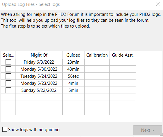
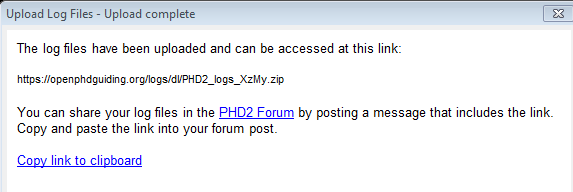
One of the most common responses to a request for support in the PHD2 Forum is: please upgrade to the latest version and see if the problem still exists. If you are seeing an issue in an older version of PHD2 it is quite likely that you are not the first person to encounter it, and it has already been discovered and fixed in a newer version of PHD2. For this reason, the developers of PHD2 feel that it is important to be running the most up-to-date version of the program.
Updating a program that you rely on for unattended imaging can sometimes be perceived as a risky proposition. The developers of PHD2 recognize this sentiment--we are imagers too! There is a necessary trade-off between maintaining a stable software installation and staying current with the latest bug fixes and other improvements. In some cases, camera vendors will issue "breaking" changes to their software drivers and SDKs, often because they have introduced a new camera model. This poses a problem for us because we are forced to update the camera SDK in order to support the new camera. But this also means that current users may encounter problems with a camera and drivers that have been working well, something that can only be corrected by upgrading to the latest camera drivers and the latest version of PHD2.
PHD2 achieves a balance between these two opposing needs by publishing two series of software releases. The development releases contain the latest ongoing bug fixes and feature improvements and are tested by the developers--usually during actual imaging time--before being released. Users who choose to run the development releases will get the latest bug fixes and newest features. Development releases have names like "2.6.3dev6" indicating, for example, the 6th development release after the 2.6.3 major release.
Periodically, after a development release has received more test time, it will be published as a major release. For example, 2.6.3dev6 could be published as major release 2.6.4.
PHD2 has an option to automatically check for software updates. We recommend enabling this option to help keep your version of PHD2 up to date. When the automatic check option is enabled, PHD2 will check for updates in the background when PHD2 starts. If new updates are available, PHD2 will give you the option to install the new version. Enabling the automatic check for updates will not interfere with the ordinary operation of PHD2, including automated operation. It is also safe to leave the option enabled if you are imaging in the field without internet connectivity. If PHD2 cannot check for updates, it will wait until the next time it is started before trying to check again.
Regardless of whether you allow PHD2 to automatically check for updates at startup, you can always manually check for updates by clicking "Check for updates" from the Help menu.