Tools and Utilities
Polar Alignment Tools
Auto-select Stars
Calibration_Assistant
Guiding Assistant
Calibration Review and Modification
Manual Guide
Star Cross Tool
Meridian Flip Calibration Tool
Comet Tracking
Lock Positions
PHD2 Server
Polar Alignment Tools
PHD2 offers three different polar alignment tools. The three approaches share the same basic
objective: to help you physically align the RA axis of your mount to the
celestial pole. These polar alignment
tools are different from the “two-star” or “three-star” alignment procedures
that are part of many popular go-to mounts.
The mount software routines are generally focused on optimizing go-to
operations by adjusting the slewing/pointing operations to compensate for various errors
in the mount, including polar alignment error.
They generally don’t involve physical adjustment of the mount’s azimuth
and altitude controls, which is what is necessary for successful imaging and
guiding.
The
three polar alignment tools have different requirements and behaviors,
as summarized in the table below. The accuracy and speed columns
show values in the range of 1-3, where 1 is lowest and 3 is highest.
| Method | Accuracy | Speed | Sky View | Other |
| Traditional drift alignment | 3 | 1 | East or west horizon
Meridian/celestial equator | Most slewing
Axes measured/adjusted separately |
| Static polar alignment | 1 | 3 | Polar region | Requires identification of polar region stars
Minimal slewing |
Polar drift alignment
| 2
| 2 | Polar region
| Minimal slewing
|
The original polar alignment routine, drift alignment, is
still considered by most to be the “gold standard” for accuracy. Partly, this is because it directly measures
the thing you’re interested in: the amount of drift that will be caused by
mis-alignment of the RA axis on the celestial pole. The drift alignment tool requires use of only
one visible star at a time, and identification of the star is unnecessary. But the procedure can be time-consuming,
especially for beginners, because each mount axis must be adjusted separately
and the telescope will need to slew over a fairly wide area. Also, it works best if you have clear views
of the celestial equator/meridian intersection and an area around 30 degrees
above either the eastern or western horizon (azimuth 90 or 270 degrees). For imagers who are rushing to set up each
night or have a limited view of the sky, these requirements may be unappealing.
The second alignment option, static polar alignment,
addresses these concerns by taking a different approach. It specifically trades off some accuracy
to optimize the speed of the process. It
requires only a clear view of the northern or southern polar region, and it
facilitates adjustment of both mount axes at the same time. It is therefore a bit more intuitive and quite
likely to be quicker to complete. It
does require visibility and identification of several stars near the pole, but
the tool makes that reasonably easy assuming your sky conditions are good
enough to see the stars.
The third alignment option, polar drift alignment, is probably the
simplest one to perform at the expense of a bit of accuracy and speed.
It
requires a clear view of the northern or southern polar region, and it
facilitates adjustment of both mount axes at the same time. Minimal
user input is needed so it is very simple to use.
The three techniques are described in detail in the following
sections. Imagers should probably
experiment with them and choose the one that best suits their
needs. The importance of alignment
accuracy is often over-emphasized, so users need to keep things in
perspective. Most declination drift can
be well-managed by PHD2 guiding assuming the mount behaves well and doesn’t
have a lot of declination backlash.
However, at some point, the amount of polar alignment error can create
field rotation in the images, something that can’t be corrected. The larger the imaging sensor and the closer
to the pole the target is, the more field rotation can be an issue. You can compute the expected field rotation
using an online calculator such as this one:
http://celestialwonders.com/tools/rotationMaxErrorCalc.html
The calculator can help you decide how much accuracy is
“good enough” for your situation. It’s
also important to remember that any of the procedures can be limited by
the
precision of the adjustment mechanisms on the mount and your ability to
tighten them sufficiently to keep things from moving around as you slew
to various parts of the sky.
Auto-Select Stars
Automatic guide
star selection can be accomplished in several ways. The simplest way
is to click on the 'Auto-Select Stars' icon in the main window,
next to the 'Guide' icon. Auto-selection can also be triggered by using
the keyboard
shortcut of <Alt>S or by clicking on the 'Auto-select stars' item
under the 'Tools' menu. Taking any of these actions tells PHD2
to scan the current guide image
and identify stars most suitable for guiding. PHD2 will try
to select stars of sufficient brightness that are not
saturated, have sufficient size, and are not too near other stars
nor too close to the edge of the
frame. The
selected stars may appear fairly dim on the screen, but that's not
important - just adjust the gamma slider on the main window if you feel
the need to see them.
The auto-select function will nearly always do a better
job than
you can by just looking at the display, and it is the only way to invoke
multi-star guiding. In many cases, a star
you choose interactively is at or near saturation and will produce
sub-par results. You can use the Star Profile tool
to examine the properties of the primary (brightest) selected star,
however it was chosen.
To get the best results from Auto-Select, you should
use either a bad-pixel map or dark library and specify a
Min-HFD value (Advanced Settings/Guiding tab) to reduce the
likelihood of PHD2 mistakenly choosing a hot pixel. It also works
better if you set the option to measure saturation by Max-ADU value
(Advanced Settings/Camera tab), assuming you know or can determine the
maximum ADU value of your camera. For example, a 16-bit guide
camera will have maximum ADU values approaching 65000, an 8-bit camera
will saturate near 255. Camera images are always delivered as
either 8 or 16-bit quantities by the camera drivers, regardless
of the internal electronics of the camera (e.g. 12 or 14-bit ADCs).
To
de-select the star and continue looping exposures, just shift-click on
the 'Auto-Select Star' icon or shift-click anywhere in the image
display window. This can be useful if you're using sub-frames and
want to return to a full-frame view of the guider images.
Calibration Assistant
The
Calibration Assistant (CA) provides the best means for completing an
accurate calibration. It does this by helping you
avoid operational problems that can interfere with the calibration
process. This is particularly important for beginners who
often struggle with both operational and mount-related problems and
then can't understand what went wrong. The CA is also useful to
experienced imagers who want to complete a calibration as quickly
as
possible without having to think about the procedural details.
There
are three
basic phases of a calibration assistant session: 1) slewing the
telescope to an optimum sky position and pre-clearing any Dec
backlash,, 2) starting the calibration and waiting for its completion,
and 3) evaluating the results and providing an overall quality
assessment. If the quality is judged to be less than "good",
additional explanations are offered that are specific to
whatever problems arose. In order to use the CA, you need to be
using a 'mount' or 'aux-mount' connection that can provide pointing
information to PHD2 - typically an ASCOM or INDI driver but possibly
the "Ask for coordinates" tool for very basic mounts. If the
mount can't be slewed through one of these connections, you can still
use the CA as a guide for how to point the telescope and then let it
start the calibration and assess the results.
The CA is only usable in interactive
mode, it doesn't come into play when guiding is being controlled by a
separate imaging application. The CA can be explicitly started
using the 'Calibration Assistant...' entry under the 'Tools' menu.
The CA will handle any necessary steps of starting/stopping camera
exposures and doing an auto-find for guide stars so you can start it
whenever you want. If calibration is started by doing a
shift-click on the guiding
icon, you may see a new dialog if the scope isn't pointing in a
suitable area of the sky:
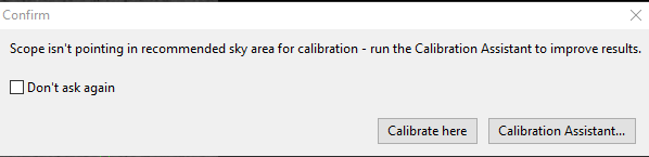
This
dialog shows the button to start the Calibration Assistant, the
option you should generally choose. If you click, instead,
on 'Calibrate
here', the CA will not run and calibration will proceed as it has in
the past. Once the CA is active, you will see a non-modal dialog
window like this:
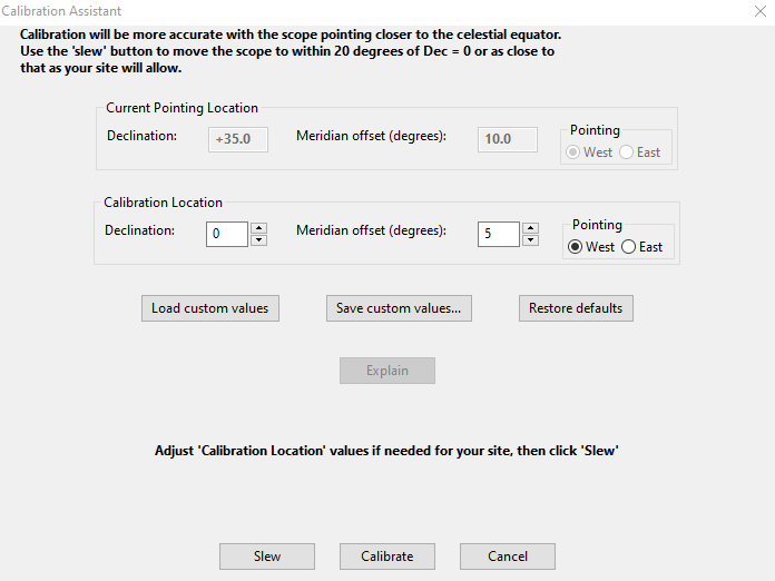
The explanatory text at the top of the window will change depending on where the scope is currently pointed.
Slewing Operations
The
CA will always propose to slew the telescope to a location near Dec=0
(the celestial equator)
and 5 degrees east or west of the central meridian. The choice of
'east' or 'west' is based on where the mount is currently pointing in
order to avoid triggering a meridian flip. Users of fork mounts
aren't affected by meridian flips, and any flip-related messages
in the user interface can be
ignored. If you are
like most users, the recommended calibration location will be the best
choice and you should simply click on the 'Slew' button to move
the telescope to that location.
Obviously, you must insure that the scope can perform the slew
safely. If you have obstructed views of the sky at your site, you
can adjust the
calibration location by changing the values in the 'Calibration
Location' group of controls. You should be conservative about
doing this or you will defeat the purpose of using the CA. If you
regularly have the same visibility limitations, you can save your
modifications using the 'Save custom values...' button and then re-use
those values on other nights by clicking on the 'Load custom values'
button. Clicking on the 'Slew' button will result in two
successive slews of the scope: the first to roughly position it
slightly south of the calibration location, and the second to move it
north by one
degree in order to clear any Dec backlash. This action,
alone, will eliminate the most common source of problems that people
have with calibration. When the slewing is completed,
the existing calibration is still valid - it won't be cleared until you
click on the 'Calibrate' button. This means the CA can also be
used as a convenient means for slewing the telescope to a location
that works best for Guiding Assistant diagnostics or for measuring
the
performance of your mount. The CA dialog will remain open until
you
click on the 'Cancel' button so its functions can be used iteratively.Calibration
When
you click on the
'Calibrate' button, the CA will first sanity-check
settings such as mount guide speed and the calibration step-size value.
If these values don't look right, you will see another dialog
warning you of the specific problem. If the calibration step-size
is wrong, the CA will offer to recalculate ('Recalc') it for you.
If the mount
guide speed is too low, it will advise you to increase it to at least
0.5x sidereal. This isn't done through PHD2; you will need to
adjust it in the mount driver or via the mount hand-controller. The CA
sanity-checking dialogs look this this:
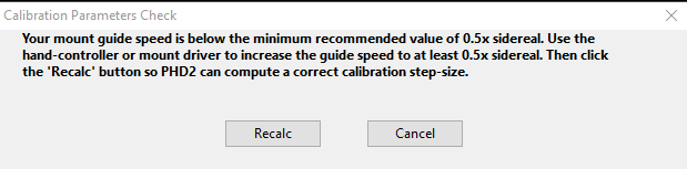
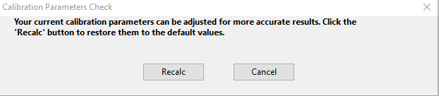
As with the other CA messages, you are strongly encouraged to follow the recommendations.
After this sanity-checking is complete, the CA will
trigger the normal calibration process. You can move the CA
window out of the way if you want to watch how the calibration
proceeds. When the calibration completes, the CA will use various
metrics to judge the results and will display an overall assessment of
'poor', 'acceptable', or 'good'. In some situations with poor
site visibility or mechanical problems with the mount, it may not be
feasbible to achieve a 'good' result. 'Acceptable' results are
just that - good enough to continue guiding, not something to obsess
over, but something to keep in mind if you want to later improve your
guiding results. 'Poor' results can still be used in most cases but you
should expect that guiding results will never be very good. If the
calibration fails altogether - too little movement, lost stars, etc -
you should remedy the problem and repeat the calibration.
If
the calibration result is less than 'good', you can click on the
'Explain' button to see a description of what problems were present and
what things you can do to get a better result. If you have
followed all the CA instructions, the explanations are likely to help
you better understand issues like 'orthogonality error', 'unexpected
rates', and other situations that trigger calibration
alerts.
Clicking
on the 'Cancel' button only closes the CA window, it doesn't cancel or
stop any operations that are happening in the PHD2 main window.Guiding Assistant
The
Guiding Assistant (GA) is an instructional tool to help you measure
current seeing conditions and the general behavior of your mount and
guiding
subsystem. When it's run, it temporarily disables guiding output
and measures the ensuing motion of the guide star. This can help
you
see the high-frequency motions caused by seeing (atmospheric)
conditions. These cannot be corrected by conventional
guiding because they occur at a much higher frequency than you
can measure. Trying to correct for them with conventional
guiding is often called "chasing the seeing" and usually leads to
poor results. Avoiding it is best accomplished by
setting a minimum-move level that will cause PHD2 to ignore most of
this high-frequency behavior. The GA can also show
you other behavior of your system such as overall drift
rates in right ascension and declination as well as peak-to-peak and
maximum-rate-of-change measurements in
right ascension,. While these things can usually be "guided out",
measuring them can be helpful if you want to improve the underlying
performance of the mount - for example, by applying periodic error
correction in RA. The GA can also measure the declination
backlash in your system if
you select that option in the user interface. If you're not
familiar with these terms, you can find a short discussion here: Common Mount Problems
When
you start the Guiding Assistant, its behavior depends on whether
you are already guiding. If guiding is active, the initial screen
will look like this (with different data values of course):
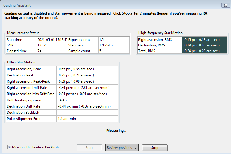
The
topmost field in the form always shows what the GA is doing and what
action you should take, so you should always look there first if you
don't know what's happening. In this case, the measurement
process has been started automatically and you should simply let it run
for at least two minutes. The text field immediately above the
buttons also summarizes what's happening. The three buttons are
enabled or disabled based on the operating state of the GA. In
this case, 'Start' is disabled because the measurement is already
underway.
If you launch the GA when guiding is inactive, the initial form will look different:
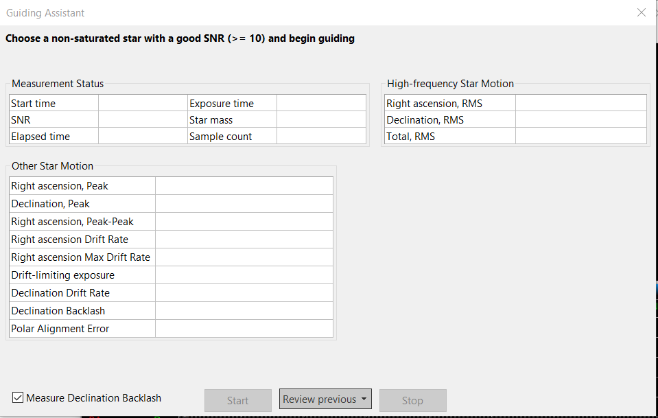
In
this case, you'll need to first start guiding in PHD2 - start looping,
auto-select a star, and guide. Once that's done, the 'Start' button in
the GA will be enabled and you can begin measurement.
When
GA measurement is active, guiding commands will be disabled, so the
star
will appear to wander around on the display - this is entirely normal.
As guider images are acquired, statistics are computed and
displayed in real-time in the user interface. After about
two
minutes of data collection, the more volatile measurements like
High-frequency Star Motion and Polar Alignemt Error will usually
stabilize and
you will probably have reasonably accurate measurements. If you
want to get a
more accurate measure of your polar alignment error
and any uncorrected periodic error in RA, you'll need to let the GA run for up to 10 minutes. Also, the computed polar
alignment error is sensitive to the current scope declination. To
get the most accurate measurement, you should point the scope to within
a few degrees of the celestial equator and near the celestial meridian, the same area you should use
for calibration.. When you finally click
the 'Stop'
button, this phase of the measurement process will stop. If
you've checked the box to 'Measure Declination Backlash" that process
will commence (see below). If not, guiding commands will be
re-enabled and the data collection
process will end. Other computed results will be displayed
in the lower area of the table showing overall drift rates and various
other measurements. All of these values are displayed in
units of both arc-seconds and pixels. The dialog box will look
something like this:
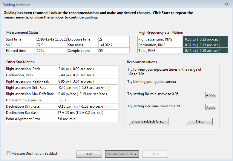
The
contents of the 'Recommendations' group on the right side of the window
reflect the results of the statistical measurements. Assuming
your chosen guide algorithms support a minimum-move property, you have
the option of automatically setting those parameters based on the
results. You can also elect to re-run the measurements or close
the dialog box altogether if you want to proceed with normal guiding
operations.
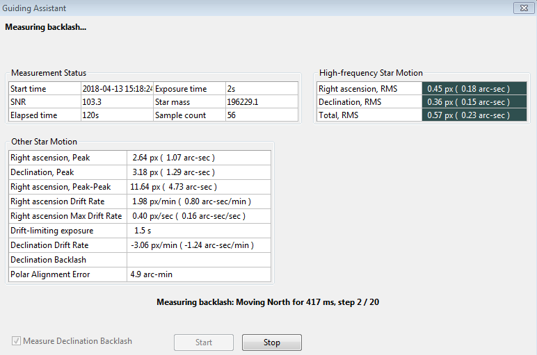
Measuring Declination Backlash (Dec reversal delay)
If
you've checked the box to 'Measure Declination Backlash',
that process will begin as soon as the baseline measurements
are completed. In other words, clicking once on the 'Stop' button
halts the baseline measurements and begins the measurement of
declination backlash. However, if the initial sampling period was
less than 2 minutes, a dialog box will appear and the GA
will continue to sample until the 2-minute period has expired. A
new group of status messages will be
shown immediately above the 'Start' and 'Stop' buttons so you can see
what's being done:
To
do backlash measurement, PHD2 will move the star by large amounts,
first in the north direction, then back to the south. There is
some risk the star will be lost during this process or the star might
already be too close to the north edge of the sensor. You
should choose a guide star that has plenty of room to move north
to get the best accuracy. You may need to manually select a single guide star if the
auto-select function keeps choosing a primary star too close to the
edge of the frame. If the star is lost because it's been
moved outside the search region, you can temporarily increase the size of that region from
the 'Guiding'
tab of the Advanced Settings dialog. A search region size of 20 pixels should work for most
configurations - just be sure you don't have multiple stars inside
the
search region. The first phase of backlash measurement tries to clear the backlash that is present in the north
direction. The GA will continue with these
clearing commands until it sees a significant and consistent movement
of the
guide star in one direction. Once this is done, the GA will issue
another sequence of commands to continue moving the star north by a
large amount.
This will take at least 16 seconds and may take longer depending
on the configuration - you can watch the status update to see what's
being done. When the north steps are finished, the GA will issue
an identical number of steps in the south direction. If there's
significant backlash in the mount, it may take a long time for the star
to start moving south, but that will usually be handled. Once the
south steps are done, the GA will try to compute an accurate
estimate of the backlash amount, corrected for Declination drift.
This won't be done if the mount never established a consistent
rate of south movement that was at least 90% of the measured rate
moving north That situation usually indicates binding in the
Dec axis or substantial imbalance, in which case a simple estimate
of backlash will be inaccurate and probably irrelevant. You
can always use the 'Show graph' button to see what happened during the
test even if no estimate is produced. When the test is completed,
the GA will try to move the star back close to its
starting position and will re-enable guiding. Again, there is
some risk the star may be lost, but this won't affect the calculations
- you can simply stop and resume guiding as you normally would.
Unlike the first phase of baseline measurements, you don't need to click on the 'Stop' button once backlash
measurement has begun. The measurement process will terminate
when all the steps have been completed, and normal guiding will be
resumed. However, you can click on the 'Stop' button if something
has gone wrong - such as a lost-star condition - and then restart when
you're ready. When the backlash tests are finished, you'll see
the results
displayed as before, with the addition of entries for the amount of
declination backlash and the measurement uncertainty (or a status line
that says the test failed):
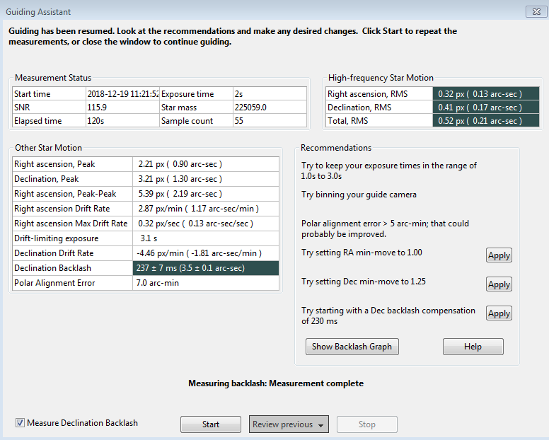
Depending
on the amount of backlash, you may see a recommendation for setting a
backlash compensation factor - 230 ms in the example shown above.
This type of backlash compensation is different from the feature offered in many mount controllers and is described here: PHD2 backlash compensation If the measured amount is less than 100 ms, no recommendation
will be made because such a small amount probably doesn't warrant any
compensation. If the backlash is very large, over 3 seconds,
you'll see a different recommendation to use uni-directional guiding in
declination. That's because trying to compensate for such large
values probably won't work very well, and the mount will probably not
be able to reverse directions quickly enough to support bi-directional
guiding. Obviously, you can reach your own conclusions based on your
experience with how the mount behaves. Before doing these
measurements, be sure to disable any backlash compensation that's
previously been
enabled in the mount software. If this isn't done, the
measurements and
any subsequent attempts at compensation by PHD2 will be invalid.
If you want to try uni-directional guiding, you can find
instructions here: Uni-directional guiding
You
can look at a graphical display of the backlash measurement results to
get a better understanding of how the mount performed even if the test failed. Just click
on the 'Show Graph' button to see a graph that might look something like
this:
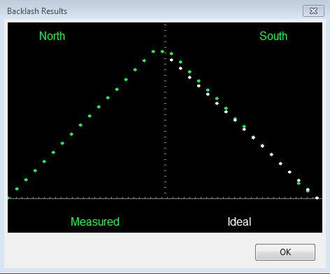
The
green points show the measured declination positions, shown left to
right, beginning with the north moves and ending with the south
(return) moves. The white points show the south-return behavior
for a perfect mount with zero backlash. In this example, there is
only a small amount of backlash as evidenced by the flattened top of
the green
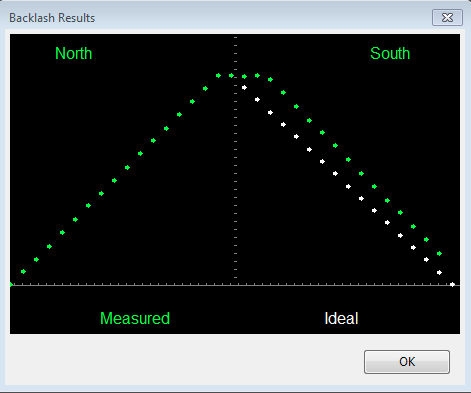
points. However, the flattened top will be more pronounced when
there is significantly more declination backlash in the mount, as in
the following example:
The 'Review Previous' button at the bottom of
the window lets you review the previous three GA results. If
you've run backlash tests at any time, at least one of the three
sessions will include a backlash measurement result. Clicking on
the 'Review' button displays a list of timestamps when a GA was run for
the current profile, so you can just select the date/time you want.
All the grid values and recommendations will be filled with the
results from the selected GA run, including active buttons for applying
the recommendations.
Calibration Review and Modification
Most of the calibration-related windows, including calibration sanity-checks, will open a window that looks something like this:
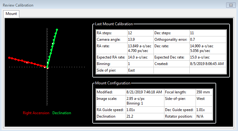
The
first thing to look at is the graph to the left, which shows the guide
star
movements as a result of the guide pulses that PHD2 sent during
calibration. The lines show how the RA and Dec mount axes relate
to the camera sensor X/Y axes - these lines should be
roughly perpendicular but their overall orientation is unimportant.
The data points on the lines will never be perfectly spaced or
aligned, but they should not have major curves, sharp inflections,
or reversals in direction. Particularly with longer focal length
scopes, the
points will often show scatter around the lines, but this
is normal. The solid points (west and north pulses) are used to
compute the RA and declination rates, while the hollow points show the
"return" paths of the east and south moves. These can help you
see how much fluctuation occurred due to seeing and also whether there
is a significant amount of backlash. If you are using the
"fast-recenter" option in the Advanced Settings, there will be many
fewer points shown in the east and south paths. The tabular
information to the right
shows what was known about the pointing position of the scope and the
various ASCOM settings that relate to guiding. If you are not
using an ASCOM mount and don't have an "Aux mount" specified, some of
this information will be missing. The table will also show
the expected guiding rates for a "perfect" calibration using
the same sky position and guide speed settings you used. You will
almost never achieve these ideal values, but you shouldn't worry about
them unless you see alert messages warning of suspicious values. If you didn't see
any
alert messages when the calibration completed, your results are probably
good enough. If you want to re-use a calibration for an extended
time, it is probably worth a few extra minutes to check this
information and confirm that the calibration went
reasonably well and produced sensible results. Bad calibrations
can occur even for experienced imagers and high-end mounts, so
it is good to check.
If you are having consistent problems getting alert-free calibrations, you should review the material in the Trouble-shooting section .
Other Calibration-Related Menu Options
Calibration data are saved automatically each time a calibration sequence completes
successfully. The use of the calibration data has been described
elsewhere (Using PHD Guiding),
including options for restoring calibration data from an earlier
time or "flipping" it after a meridian flip. You access these
functions using the 'Modify Calibration' sub-menu under the 'Tools' menu. Two other
calibration-related items are shown there, namely the options to
clear the current data or to enter calibration data manually. The
"clear" option accomplishes the same thing as the 'Clear mount calibration'
checkbox in the Advanced Settings dialog - it will force a recalibration
whenever guiding is resumed. The 'Enter calibration data'
option is intended for development work or for use by experts, and is mostly there for completeness.
Manual Guide
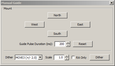
If you are encountering calibration
problems, you should be sure that PHD2's
commands are getting to the mount and the mount is responding accordingly. Or you may want to nudge the mount or
experiment with manual dithering. In the 'Tools' menu, click on
'Manual
Guide' and
a dialog will appear to let you move the mount at guide speed
in any
direction. If you have an
adaptive optics device attached, you'll see separate move buttons for
both the AO and the secondary mount. Each time you click the
button, a pulse of the duration
specified in the 'Guide Pulse Duration' field will
be sent. Holding a button down has no effect and you need to give the
mount time to respond (at least the full duration of the guide pulse)
between button-clicks. The default value is the 'calibration step-size'
set in
the Advanced Settings dialog. If you are debugging
mount/calibration
problems in the daytime, listen to (rather than watch) your mount to
determine if it is getting
the commands from PHD2. The idea here is just to determine if the
mount is responding
to PHD2's guide commands. You won't be able to see the mount move (it's moving
at guide speed)
but you may be able to hear the motors. Other options include watching
the
motors and gears or
attaching a laser pointer to your scope and aiming it at something
fairly far away (to amplify your motions). A better approach
for nighttime testing is to run the "star-cross" test described here.
Beginners often make the mistake of confusing the slewing-type
operations done by planetarium and imaging applications with the
completely different guiding operations done by PHD2. Knowing that an imaging app can slew your telescope correctly
doesn't tell you anything useful about whether the mount is guidable.
Dithering
is used primarily with image capture or automation applications using the PHD2 server interface. However, you can do
manual dithering or experiment with dither settings using the controls
at the bottom of the dialog. The 'dither' amount field at the
left controls the amount the mount will be moved, in units of
pixels. You can scale this amount - i.e. multiply it by a
constant - by using the 'scale' spin control to the right. These
two controls establish a maximum amount of movement that will be used
for dithering - the product of 'scale' x 'dither'. When you click
on the 'Dither' button, PHD2 will move the mount by a random amount
that is less than or equal to the limit you have set, in one of the
north/south/east/west directions. The 'RA Only' checkbox will
constrain the dither adjustments to only east or west. Obviously,
if you are doing a manual dither in this way, you'll want to be sure
your imaging camera is not in the middle of an exposure.
Star-Cross Tool
The Star-Cross tool can help you test the mount's response to guide commands as described in this Trouble-shooting
section. Although the test is easy to perform manually, you may prefer
to use this tool. The star-cross tool will show the following
dialog:
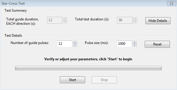
This test presumes you're using the main image camera to expose the image, and PHD2 doesn't know what image scale is being used for that.
You need to be sure the settings are large enough to show a
distinct
pattern on the main camera image but not so large that all the stars will move
out of the field of view. The default settings should work well
for most set-ups but you can adjust them as needed. The important
thing is to get a clear record of the movement of the stars in the main
camera image and to save that image in a raw, uncompressed format (eg.
FITs or uncompressed TIF). During this test, looping will be
active but no guide star will be selected, and it doesn't matter if
individual stars move out of the guide camera frame. Looping is
activated just so you get some quick visual feedback on whether the
mount
is moving.
Meridian flip calibration Tool
The meridian flip calibration tool (wizard) is used to automatically determine
the correct value for the setting Reverse Dec output after meridian flip.
Running the wizard involves two calibrations -- one with the telescope
on the East side of the pier, and one on the West. You will be
instructed to slew (meridian flip) the telescope when needed.
This only needs to be done once for each type of mount you use. You must carefully follow all the instructions shown in the wizard's dialogs - failing to do so or taking short-cuts will invalidate the results and will siimply waste time.
Comet Tracking
One way to image a comet is to have PHD2 use the head of the comet as the guide
"star", but this approach may not always work. For example, the head
of the comet may not present a star-like center suitable for
guiding. Or, when using an off-axis guider, the comet may not even be
visible in the guide camera.
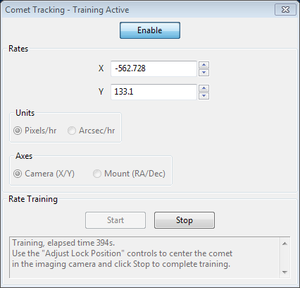
PHD2 provides a Comet Tracking tool for use when guiding on the comet
itself is not feasible. The idea is to guide on an ordinary star, but
to gradually shift the lock position to match the comet's motion,
or tracking rate.
There are a three different ways to provide the comet tracking rate to PHD2.
- Some planetarium applications, especially Cartes du Ciel, can send the rate directly to PHD2;
- You can enter the tracking rate manually, or,
- You can train the rate in PHD2 by following the comet for a period of time in the imaging camera.
To enter the rates manually, you would select "Arcsec/hr" for units and
"RA/Dec" for axes, then enter the rates from the comet's ephemeris.
If you are getting the rates from the MinorPlanetCenter web site,
you should choose the option for 'Separate RA and Declination
coordinate motions'. PHD2 will automatically adjust the rates to
compute the apparent motions in the sky.
Comet rate training works like this:
First, center the comet in your imaging camera. If your imaging
application has some kind of reticle display, you should use that to
note the precise position of the comet on the imaging sensor. Once
this is ready, select a guide star in PHD2 and start guiding. Next
click "Start" in the Comet Tracking tool to begin training.
Take a continuous series of short exposures in your imaging camera
using your imaging application's Frame and Focus feature. Over time,
the comet will drift away from the starting location. Use PHD2's
"Adjust Lock Position" controls to move the comet back to the starting
location. You may have to experiment a bit to determine which way the
comet moves on the imaging camera sensor in response to the
Up/Down/Left/Right controls in PHD2. You may find it useful to enable
the "Always on top" button in the Adjust Lock Position window so the
controls stay visible on top of your imaging application.
PHD2 will quickly learn the comet tracking rate as you re-center the
comet. Once you are satisfied that PHD2 is tracking the comet, you can
click Stop to end the training. PHD2 will continue shifting the lock
position to track the comet until you disable comet tracking by
toggling the Enable/Disable button.
You can practice the comet training technique using the built-in
camera simulator. Check the "Comet" option in the Camera Settings dialog, and the
simulator will display a comet. Use a bookmark to mark the comet's
starting location, and use the Adjust Lock Position controls to move
the comet back to the bookmark location.
Lock Positions
PHD2 normally
sets a 'lock position' where the guide star is located at the end of
a calibration. Depending on the details of the calibration
sequence, this may not be exactly where the star was located at the
start of calibration - it could be off by a few pixels. If you
are trying to precisely center your target after calibration, you may want to use a
'sticky lock position.' You do this by clicking on your guide
star before calibration, then
clicking on 'Sticky Lock Position' under the 'Tools' menu. After
calibration is complete, PHD2 will continue to move the mount until the
star is located at the sticky lock position. So you may see
an additional delay after the calibration while PHD2 repositions the
scope at guide speed. The sticky lock position will continue to
be used even as guiding is stopped and subsequently resumed unless you change the lock point through actions such as dithering.
Again, this insures a rigorous positioning of the guide star (and
presumably your image target) at the expense of delays needed for PHD2
to reposition the mount.
If
you need to fine-tune the position of the guide star on the
camera sensor after guiding has begun, you can use the 'Adjust Lock
Position' function under the Tools menu:
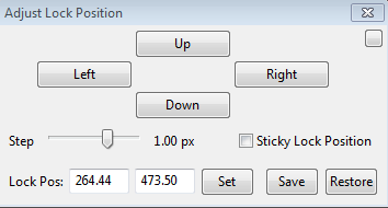
You
can nudge the guide star in small increments (at guide speed) or you
can move it by a larger amount by typing in a new lock position
and clicking 'Set'.
Clicking on the up/down/left/right buttons will cause the lock
position to be shifted in the corresponding direction by the amount
shown in 'Step', and the revised lock position will be displayed
If you type in a new lock position, you run the risk of losing
the guide star if the new position falls outside the current
search region. This tool is useful if you need to achieve
precise positioning of either the guide star or the imaging target, for
example with spectroscopy - but it is unnecessary for most users.
PHD2 Server Interface
PHD2 supports third-party
imaging and automation applications that need to control guiding
operations. In recent years, many new automation applications
have become available and nearly all of them use the PHD2 server
interface. By using this API, these applications can control all
the typical activities relating to PHD2 guiding: starting/stopping,
pausing/resuming, dithering/settling, calibrating, profile-loading, and
many others.
To use automation applications of this type, you should be
sure the PHD2 'Enable
Server' option under the 'Tools'
menu is enabled. With the option enabled, the operating system
firewall must be configured to let PHD2 use network connections,
something that is typically done as part of the PHD2
installation. Documentation for the
server API is available on
the PHD2
Wiki.